Time-tested Techniques for Today's Technology
A change in technology can cause apprehension or relief. Compare the Ford VV carburetor to Port Fuel Injection or an older, strictly hydraulic transmission to a modern, computer-controlled unit. In 1968, if a vehicle shifted late or harsh, we adjusted the TV linkage or vacuum modulator. Today you can diagnose and alter shift quality from the driver's seat or from your office using a wireless reflash. When new technology comes along there is a learning curve, but most would agree that the new is better than the old.
This technology transition is reflected in the current move from the hydraulic valve body to the Mechatronic (mechanical/electronic) control assembly. The assembly is both valve body and TCM rolled into one, located inside the transmission. The TCM will be loaded with a vehicle application upon installation, then proceed to adapt to changes in clutch fill and exhaust requirements. Feedback from multiple speed sensors is required to control clutch fill and exhaust rates across as many as 8-gear ratios. In addition to all that complex control capability, features such as skip-shift timing, clutch overlap and multi-vehicle, plug-n-play applications add to the complexity. All that technology is enveloped in an electro-hydraulic control unit, similar in size to the C-6 valve body (Figure 1).
 |
 |
The intent of this article is to offer some precautions and to outline existing valve body test procedures that can be carried over to the Mechatronic. In older, 3-speed applications, drivability relied upon the switch action of shift valves: they stroked and remained inboard or outboard. In current 6- and 8-speed applications, clutch control requires valve modulation and flow control. The valves and solenoids become active early, often in preparing for the next shift, and this frequent activity takes a toll on valve bores and solenoids.
- When testing in the vehicle, check the TCM with your scan device first.
- Pull all codes from the TCM and other modules which might influence the TCM, such as the engine controller, ABS, air conditioning, etc.
- Check power sources (battery and bus) during cranking and as accessories operate.
- If your scan tool is CAN bi-directional, control the solenoids and compare amperages of similar designs.
- When no codes are present and the drivability issue is repeatable, check for reflash programs.
Testing at the bench should include looking for signs of damage from heat and vibration or of chemical attack by water or additives. If the fluid is discolored or there is clutch material in the pan or filter, inspection should include a water or anti-freeze test (Figure 2). One method to identify water is to place a few drops of the ATF on a hot plate. A sizzle will occur with moisture, but with pure ATF it will smoke and burn-off. Glycol test kits are
available from Mercedes under Part No. 000-989-009 and Part No. 000-989-0014 or
from ESP Chemicals under Part No. HI 3859.
 |
 |
Loose terminals or overheated circuits and solenoids created by vibration should be evaluated by a test that loads the circuit. When using electronic test controllers, tap and wiggle on the TCM and solenoids to interrupt circuits during the circuit test. In some instances, heating and cooling the TCM can identify weak circuits. Several manufacturers require the elimination of Electro-Static-Discharge (ESD). This involves conductive floor covering and personal grounding straps to prevent static discharge into the TCM.
Component testing is possible in some Mechatronic units because the circuit board with the TCM can be separated from the solenoids (Figure 3). In others, the TCM is glued to the casting (Figure 4). Solenoids should be demagnetized, cleaned and flow tested. In some instances, each solenoid flow rate is programmed into the TCM and the solenoid cannot be exchanged. In others, the TCM has enough range of adaption to allow for solenoid replacement. Any cleaning or swap may require a drive-cycle relearn (Figure 5).
A clutch piston travel and free clearance test is required because of the clutch-to-clutch shifting in Mechatronic units. The TCM has a specific range of adaption before it sets a code or corrects drivability. Valve bore leaks, excess or insufficient clutch tolerance can exceed that range of adaption.
Methods of Testing Valve Bodies
1. Air Test Plates

Air Test Plates allow a leak-down test on each valve bore independently and offer an overview of what will be required to service the valve body before starting the job. With a test cycle of less than 10 minutes, Air Test Plates also can be used to sort cores. This test is listed first because it does not require cleaning or disassembly of the valve body.
Air testing requires a regulated pressure chamber with a calibrated flow meter and gauge to measure pressure drop across the valve. Dedicated test locations for specific circuits are predetermined and easy to locate.

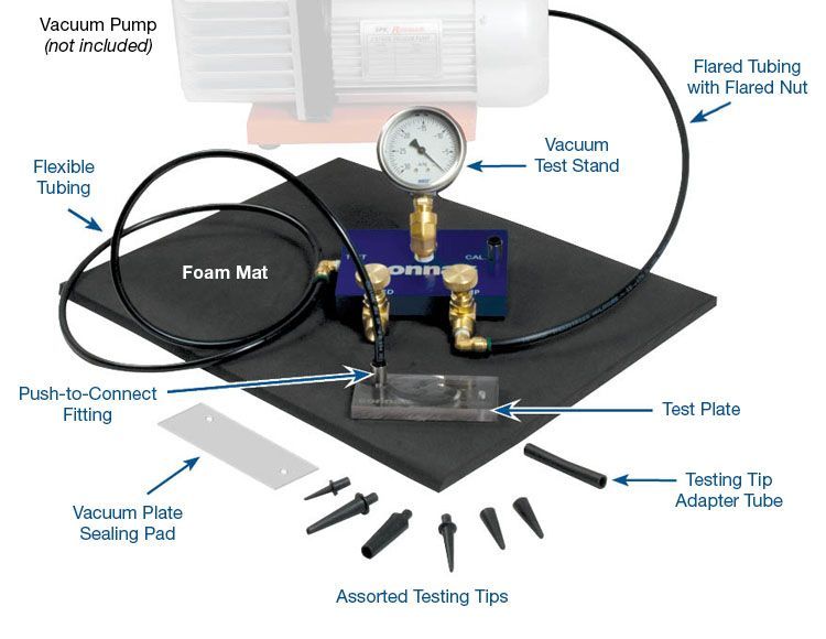
2. Vacuum Testing
Vacuum testing is more effective than a Wet Air Test because it has a measurable outcome. A vacuum pump is tied to a calibration stand, which allows for subtle adjustment. Although less expensive than Air Test Plates, vacuum testing does require operator experience to locate the proper point in the circuit, seal it effectively and establish pass/fail standards for specific vacuum equipment. It also requires more preparation than using Air Test Plates, as the valve body must be cleaned and dried beforehand.
3. Wet Air Testing

The Wet Air Test (WAT) is the traditional air test described in service manuals for clutch circuits with the addition of fluid. The process also can be used for a valve bore, solenoid circuits and line pressure integrity testing.
Wet Air Testing involves filling a cavity with ATF and pushing that fluid with regulated air pressure. A worn bore will allow the fluid to escape past the valve without building up sufficient force to push the valve. In a good bore, the valve will either stroke before the fluid escapes or it takes a longer time for the ATF to leak. Because there must be valve-to-bore clearance for the valve to stroke, fluid will eventually be forced around the spool by the air pressure. Once the fluid is pushed out, only air pressure remains and that air aggressively leaks past the valve.
The WAT uses a regulated air supply of 30-60 psi, a controllable air nozzle and some method to enclose a circuit. That enclosure can be a rag, a finger, a test plate, or a handmade tool such as the modified solenoid in Figure 6. Judging the pass/fail in time required to push the fluid will take experience. Rebuilders should test numerous valves from both good and worn bores to gain familiarity with this procedure.
4. Deflection Tests
Sonnax tech articles sometimes refer to the "Sag-Wiggle-Deflection" test. This refers to positioning either the OE valve or a tool that matches the diameter and length of the valve spool into the operating position and measuring deflection. Deflection can be measured and used as a definitive go-no-go test (Figure 7). The process requires some calculation and measuring tools to define the pass/fail standard.
 |
 |
5. Visual Inspection
The visual inspection process is placed near the end of this list because the valve body must be completely disassembled for a proper visual inspection. It requires the least amount of tools, but more time and experience (Figure 8).
The bore also will wear at both ends due to the spring and fluid loading the spool onto the bore. The highest rate of wear occurs in the area where modulated valves cycle within the bore.
6. Hydraulic Test Stands
The hydraulic valve body test stand (VBT) is last on this list due to cost. The VBTs mate the electro-hydraulic elements of the valve body and run off external controllers. In earlier solenoid controlled valve bodies, an external computer would test the solenoid circuitry first, then operate in sequence to duplicate on-car shift strategy. Later units with internal TCM and CAN control have increased that operating complexity. Designated test bench CAN controllers have been developed to operate the Mechatronics.
Hydraulic test stands are very effective, but you have to be mindful that when the valve body does not work, it requires the processes previously listed to isolate the issue. You also must deal with the fact that the vehicle has changing load, temperature and other factors that cannot be duplicated on a VBT. To duplicate some of the on-car variables, VBT testing and data can include the following: varied fluid temperature, special viscous test stand fluid, varying input pressure and flow, varied solenoid control strategy and timed clutch flow/application data. Requirements for hydraulic test stands will continue to change along with the test plates and harness.
Valve Body Testing Guidelines
Although it's not a requirement, the valve should be positioned where it operates to obtain the best result from a vacuum test. Modulated and regulating valves will not wear in the position you see at the bench – they will operate and wear-in at partial stroke and should be tested there if possible.
When a valve body has been machined on both sides, possible vacuum test locations may be exposed on each side. To enable vacuum testing on castings with both sides machined, a foam pad can be purchased to set the casting on and seal the other side.
 |
Sonnax offers a Vacuum Stand Test Kit. Click on VACTEST-01K for more information.
This article was originally published in the Sonnax Transmission Products Catalog, Volume 8.
Related Parts
Required
Recommended
Vacuum Test Stand Kit VACTEST-01K
-
Helps cure:
- The need for a quick, easy & repeatable method to test valve & bore wear
While Sonnax makes every effort to ensure the accuracy of technical articles at time of publication, we assume no liability for inaccuracies or for information which may become outdated or obsolete over time.